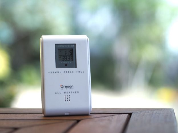
A while ago, I bought a set of Oregon Scientific weather station on special. The package came with the clock and temperature display unit (BAR283) and a remote temperature sensor (RTHR328N), which is normally put outside of the house. The remote sensor then regularly sends temperature and humidity wirelessly to the display indoors. It has been a dream of mine to tap into the temperature data sent over the air and log it in database. Fortunately, there are a few tutorials online (jeelabs instructables) online and blog posts of people who have done the exact thing successfully.
To receive the signal, you need a Amplitude-shift keying (ASK) 433.92MHz receiver. I bought the Aurel AC-RX2 on advice of one the blog posts, but in reality, there are probably better 433.92 receivers such as the RXB6 as documented here.
To get the best reception, you need an antenna. I used a 17.2cm wire for the antenna. The full wire up of the Arduino and AC-RX2 is shown below:
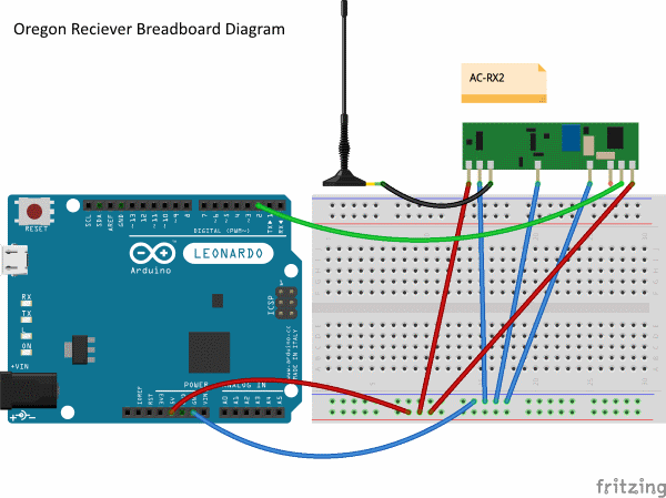
Breadboard diagram
Data is connected to Pin 2.
I downloaded the source code and loaded onto my Arduino, unfortunately, nothing came out of the console. Changing pins and rewiring didn’t yield anything useful – It just would not work. The source code was not straightforward to understand and it wasn’t like I could just add breakpoints and step through the code. That’s when I decided that I needed to start from scratch. Fortunately, the Oregon Scientific protocol is quite well documented here.
The first thing I decided to do was to make sure that data is actually coming through to the output pin. I attached a USB logic analyser and used PulseView to see if there were any data coming through. Sure enough there was, but there were a lot of data which meant nothing to me. Removing the antenna, that was a lot less data coming through, which proved that everything was hooked up correctly.
In the protocol, there were some samples of what the signal should look like. It was a Manchester encoded signal on a 1024Hz clock. The other consideration was that the sensor was not sending data all the time, but only at certain intervals. Know the exact moment that data was sent would be key to identifying the signal. Fortunately, there was a clue in the form of an LED that would blink.
The blink would come every 106 seconds and sure enough, I got a very distinct signal when it blinked. The pattern of the signal was definitely artificial and not random.
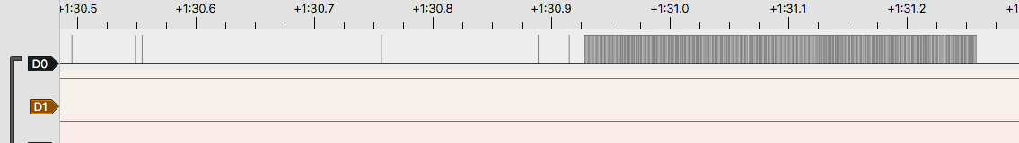
Oregon Scientific RF Signal
Decoding the Manchester encoded signal
The signal is in Manchester coding with a clock of 1kHz. This means that sampling the state every 1ms should give us a stream of bits of the transmission. Unfortunately this naive approach is error prone due to slight variations in sampling time and signal. If sampling becomes offset then errors will accumulate.
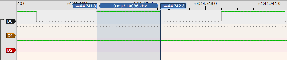
Oregon Scientific 1kHz signal
A better approach is to look at the timings of a the HIGH and LOWs and classifying each HIGH and LOW into short and long pulses. Because the signal is Manchester coded, the signal should oscillate between HIGH and LOW at least every 1ms. A long pulse should not be longer than 1ms. and a short pulse should be around 0.5ms.
However, as mentioned above, these timings can have slight variations. Therefore, we should allow for some leeway for long and short pulses.
Now that we have identified HIGHs and LOWs, long and short pulse, we need to convert them into a bit stream.
The logic I came up with is quite simple:
- A HIGH long pulse is basically a 0 followed by 1
- A LOW long pulse then a HIGH short pulse is 0
- A LOW short pulse then a HIGH short pulse should repeat the previous bit
The binary representation looks something like this:
01010101010101010101010101100110011001100110100101011001010101101001101001100110010101011001101010101010011010101001011010101010101010010110100110100101100101011
Oregon Scientific Protocol
Oregon Scientific Protocol 2 actually sends each bit in pairs, the inverse of the bit and then the actual bit. We only need to look at every second bit. To identify a valid signal, we look for the preamble and the sync, which is 16 1 bits followed by 0101. After finding this pattern, we then convert the rest of the bitstream into BCD to get the textual representation. The nibble format is LSB first.
ACD39A718030C4670000
The message is roughly broken down as follows:
9Channel 1 (A – Channel 2, B – Channel 3)
| A | Rolling Code that changes every message |
| CD3 | Device ID? |
| A71 | Rolling Code? Battery? |
| 803 | Temperature in celcius, 30.8 |
| 0 | Temperature positive/negative 0 is +, Non-zero is – |
| C4 | Checksum |
Here is the arduino sketch
const int INPUT_PIN = 2;
byte state = LOW;
unsigned long lastStateChange = 0;
unsigned long lastPulseWidth = 0;
const int MAX_BUFFER = 1024;
int bufferUpTo = 0;
char buffer[MAX_BUFFER];

int preambleCount = 0;

void setup() {
  Serial.begin(115200);
  pinMode(INPUT_PIN, INPUT_PULLUP);
  attachInterrupt((INPUT_PIN), changed, CHANGE);
}

void changed() { }

void receivePulse(unsigned long lowPulseWidth, unsigned long highPulseWidth) {

  char last = bufferUpTo != 0 ? buffer[bufferUpTo - 1] : '0';
  if (highPulseWidth >= 320 && highPulseWidth < 1350) {
    if (highPulseWidth > 615) {
      buffer[bufferUpTo++] = '0';
      buffer[bufferUpTo++] = '1';
    }
    else {
      if (bufferUpTo != 0 && lowPulseWidth >= 350 && lowPulseWidth < 850) {
        buffer[bufferUpTo++] = last;
      } else if (lowPulseWidth >= 850 && lowPulseWidth < 1400) {
        buffer[bufferUpTo++] = '0';
      } else {
        if (bufferUpTo > 10) {
          //Serial.print("low-out ");
          //Serial.println(lowPulseWidth);
          printResult(buffer, bufferUpTo);
        }
        bufferUpTo = 0;
      }
    }
  } else {
    if (bufferUpTo > 10) {
      //Serial.print("high-out ");
      //Serial.println(highPulseWidth);
      printResult(buffer, bufferUpTo);
    }
    bufferUpTo = 0;
  }

  if (bufferUpTo >= MAX_BUFFER - 2) {
    bufferUpTo = 0;
  }
}

void printResult(char* buf, int bufferUpTo) {
  char string[150];
  char result[50];
  char checksum[5];
  buffer[bufferUpTo++] = 0;
  //Serial.println(bufferUpTo);
  Serial.println(buf);

  char* remaining = buf;
  do {
    remaining = decodeBuffer(remaining, result, checksum);
    if (remaining != 0) {
      bool checksumOK = checksum[0] == result[13] && checksum[1] == result[12];
      sprintf(string, "%s - temp = %c%c%c.%c Checksum %s %s", result, result[11] != '0' ? '-' : '+', result[10], result[9], result[8], checksumOK ? "OK" : "FAILED", checksum);
      Serial.println(string);
    }
  } while (remaining != 0 && remaining - buf < bufferUpTo);
}

char* decodeBuffer(char* buf, char* strResult, char* strChecksum) {
  unsigned char result[10];
  for (int i = 0; i < sizeof(result); i++) {
    result[i] = 0;
  }

  const char* SEARCH_PATTERN = "0101010110011001";

  char* p = strstr(buf, SEARCH_PATTERN);
  if (!p) {
    return 0;
  }

  //printf("found\n");
  p += strlen(SEARCH_PATTERN) + 1;
  char* start = p;
  for (int cur = 0; *p != 0 && *(p + 1) != 0 && (cur < sizeof(result)*8); p += 2, cur++) {
    int b = cur % 8;
    if (*p == '1') {
      result[cur / 8] |= 1 << (b < 4 ? b + 4 : b - 4);
    }
  }

  for (int i = 0; i < sizeof(result); i++) {
    sprintf(strResult+i*2, "%02X", result[i]);
  }

  const int expectedMessageSize = 6;
  int checksum = 0;
  for (int i = 0; i < expectedMessageSize; i++) {
    checksum += ((result[i] & 0xF0) >> 4) + (result[i] & 0x0F);
  }

  sprintf(strChecksum, "%02X", (char)checksum);

  return p;
}

void loop() {
  // put your main code here, to run repeatedly:
  byte oldState = state;
  state = digitalRead(INPUT_PIN);
  if (state == oldState) {
    return;
  }

  unsigned long pulseWidth = micros() - lastStateChange;
  lastStateChange = micros();

  if (state == LOW) {
    receivePulse(lastPulseWidth, pulseWidth);
  }

  lastPulseWidth = pulseWidth;

  if (pulseWidth >= 600 && pulseWidth < 1350) {
    preambleCount++;
  } else {
    preambleCount = 0;
  }

  if (preambleCount == 32) {
    Serial.println(micros());
    preambleCount = 0;
  }
}
Example output:
ACD39A718030C4670000 - temp = +30.8 Checksum OK 4C
How can we connect this device with android device?
Can we put details like temperature in android app to display them in device?
There’s a few ways you could connect this to Android. You could connect the Arduino to your computer and write a program to receive the serial output with the temperature, then exposing the temperature through a REST API, which an android app that you build will then query. Even a simpler solution, you could also buy a ESP32 which has WiFi and there’s example code for an Arduino HTTP server (https://github.com/espressif/arduino-esp32/blob/master/libraries/WiFi/examples/SimpleWiFiServer/SimpleWiFiServer.ino) as the API for your Android app.
Few questions:
You coded an interrupt pin and ISr that are not used : any specific reason?
I would like to have humidity values: is the message fully decoded?
I’ve almost always a checksum error: is it a real error?
tahnks
That’s actually a good question about the interrupt. It’s been a while since I did this code, but the general idea was that the interrupt actually interrupts a sleep that I had in the loop, but evidently, for whatever reason I didn’t actually have a sleep or delay in the loop, so it can probably be removed.
Regarding humidity, my remote sensor doesn’t report humidity. If yours does, then it would probably be in the message after the temperature octets, where I’m currently assuming is the checksum – which would explain your checksum errors. See if the checksum it was expecting is the humidity value? Adding humidity should be fairly easy. Just reference the protocol documentation linked in the blog post to find out the exact message format.
I suggest not enable to pullup resistor on the DI.
The 433MHz module’s RX IC such as SYN470R or PT4303-S have extremely low output (10-20uA). See their datasheet.
The “01010101010101010101010101100110011001100110100101011001010101101001101001100110010101011001101010101010011010101001011010101010101010010110100110100101100101011” looks like a DCF77 signal. Google it.